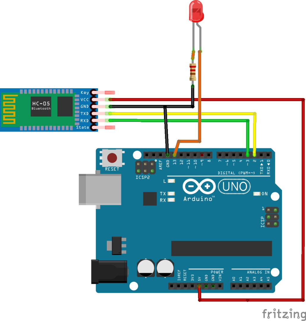

Recently a 5V small shield board has become available which drops the voltage from 5V on your Arduino to 3.3V for the nrf24L01. (The 2×4 arrangement of the pins would short out connections.) You have to use Dupont jumper wires to connect it up to an Arduino. The main downside is that the connection pins on the underside of the board are breadboard hostile. The other logic input pins are 5V tolerant which makes things much easier. It is a 3V device and the VCC pin must not be connected to 5V. There is an on-chip voltage regulator that needs a supply voltage of between 1.9 and 3.6V on the VCC pin. The user can adjust the power of the transmission to one of four levels, (MIN, LOW, HIGH, and MAX) depending on the range required. The board contains a transceiver chip from Nordic Semiconductor, a crystal, an antenna, a few support components, and 8 connection pins. It can transmit at 250bps, 1Mbps and 2Mbps on-air rates with a choice between 125 channels (1 … 125). Nordic call it a 6 data pipe MultiCeiver because it can listen to up to 6 other devices at once and transmit to them one at a time. It has a very good range, low power consumption, is cheap to buy, readily available and has several Arduino libraries available.
#Komunikasi arduino to arduino serial#
Once that message is received, it can then be viewed in the Arduino Software (IDE) serial monitor window.This is a radio Transceiver (it both transmits and receives) which operates on the 2.4 GHz Industrial, Scientific and Medical bands. Arduino 1, the Controller, is programmed to request, and then read, 6 bytes of data sent from the uniquely addressed Peripheral Arduino.

Several functions of Arduino's Wire Library are used to accomplish this. In this example, two boards are programmed to communicate with one another in a Controller Reader/Peripheral Sender configuration via the I2C synchronous serial protocol. In some situations, it can be helpful to set up two (or more!) Arduino boards to share information with each other. While the above tutorials were written specifically for the Nano Family boards, they can be adopted to any Arduino board. Connecting Two Nano 33 Every Boards Through I2C.

#Komunikasi arduino to arduino how to#
See the image below to understand how to locate the correct pins on your board.Ĭheck out the following tutorials to get a more detailed step-by-step on how to use I2C on Arduino boards: For example, the pins used for MKR WiFi 1010 are D11, D12, while the pins for UNO are D18, D19. Please note that the I2C bus is attached to different pins depending on the board you are using. When this information is sent - bit after bit -, the called upon device executes the request and transmits it's data back - if required - to the board over the same line using the clock signal still generated by the Controller on SCL as timing.īecause the I2C protocol allows for each enabled device to have it's own unique address, and as both controller and peripheral devices to take turns communicating over a single line, it is possible for your Arduino board to communicate (in turn) with many devices, or other boards, while using just two pins of your microcontroller. As the clock line changes from low to high (known as the rising edge of the clock pulse), a single bit of information - that will form in sequence the address of a specific device and a a command or data - is transferred from the board to the I2C device over the SDA line. The I2C protocol involves using two lines to send and receive data: a serial clock pin (SCL) that the Arduino Controller board pulses at a regular interval, and a serial data pin (SDA) over which data is sent between the two devices. This article was revised on 8 by Karl Söderby.


 0 kommentar(er)
